Shopping Cart


In stock, shipping within 24h.
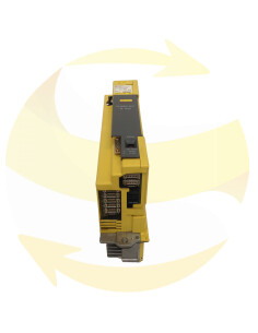
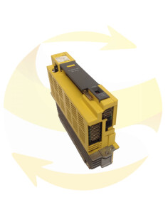
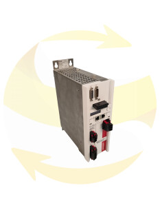
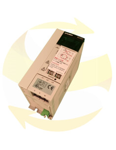
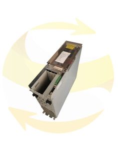
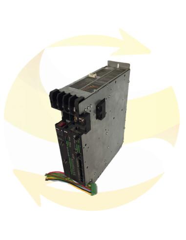
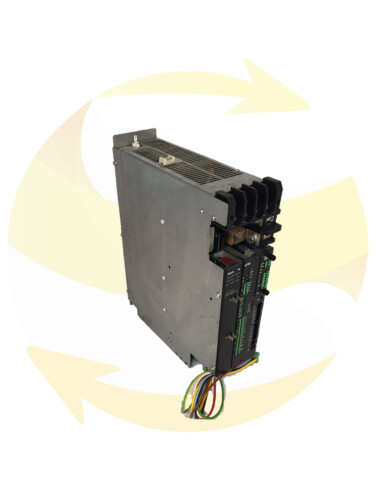
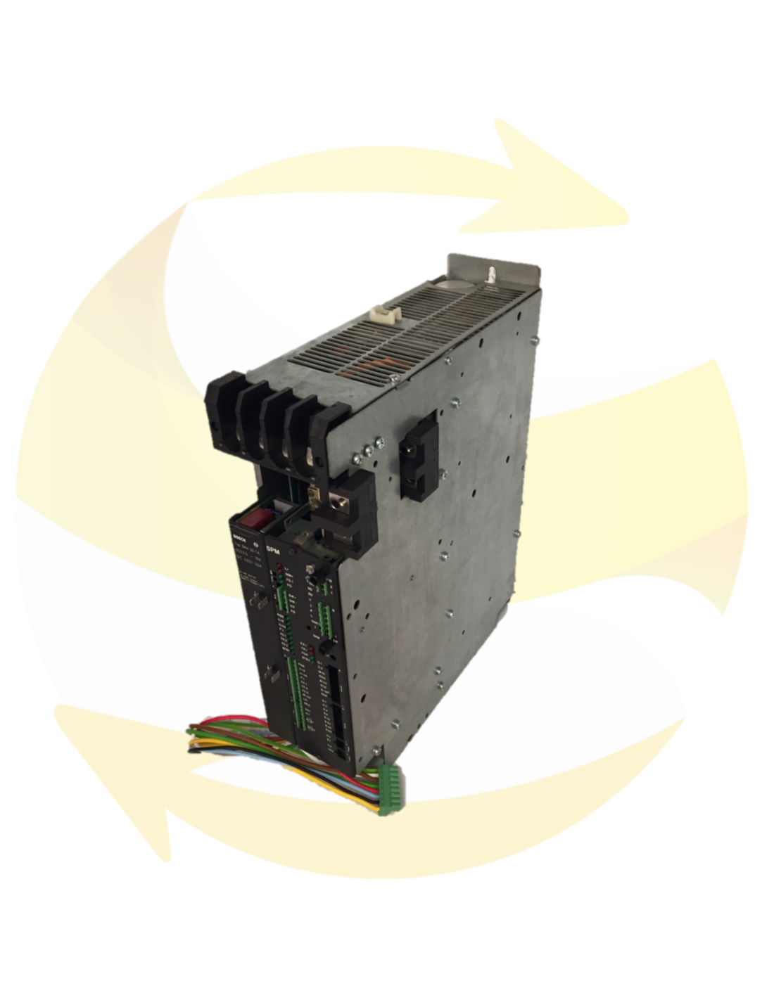
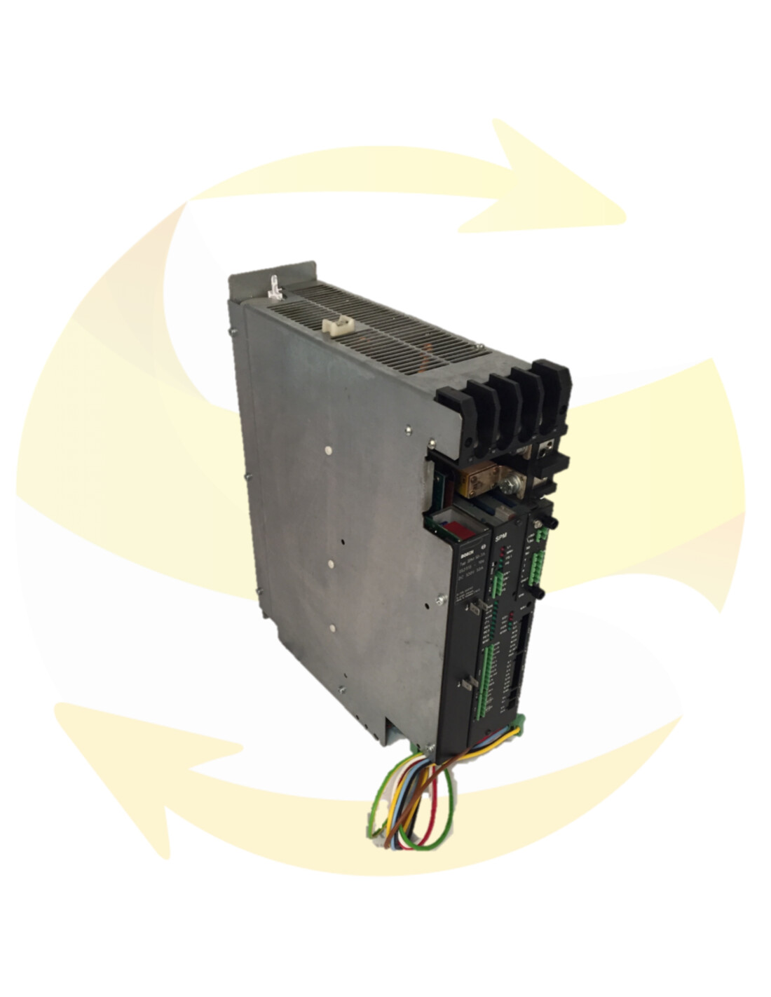
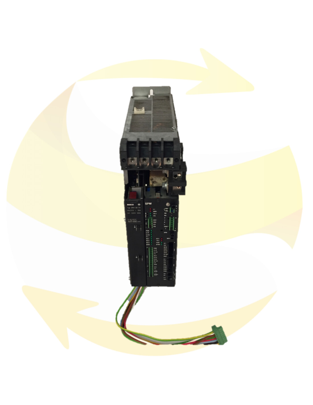
This SPM 35-TD spindle amplifier module and BOSCH brand is available in stock. This spindle drive belongs to the SERVODYN-T range.
SPM 35-TD : DC 520V, 35A
This SPM 35-TD spindle amplifier module is at your disposal to replace your defective equipment and has a guarantee adapted to your needs.

Reconditioned and tested systems
From 6 to 12
month warranty

New systems
From 12 to 24
month warranty

Reconditioned and tested systems
From 6 to 12
month warranty

New systems
From 12 to 24
month warranty

Sold for parts – no warranty

Repair will be made to damaged and defectiv units
From 3 to 18
month warranty


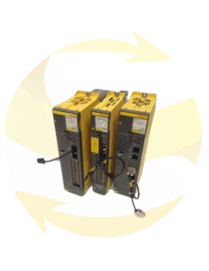
Bosch inverter systems are modular in construction. At least one power supply and one servo module are necessary to constitute an operational installation.
The power supply module generates a DC link voltage and various supply voltages (for logic and pilot circuits) from the mains (3 x 380 - 3 x 415 V).
The individual modules are connected to each other by pluggable cables which are supplied with them.
In an installation with several modules, up to 10 SM modules can be connected to a power module, depending on the size of the modules.
Since the mechanical construction and the electrical connection to the power supply module are the same as for the ASM system (inverter system for standard asynchronous motors) as well as the SPM system (inverter system for controlled spindle drives), combinations of these systems are possible (for example 3 SM modules and 1 SPM module for the main spindle)
Bosch AC inverters from the SM ..- T range allow optimum use of Bosch brushless servo motors.
Associated with a rotor position recognition function and a brushless tachometer, the servo module regulates the torque and speed of the motor.
In an inverter stage with power semiconductors, voltages and currents are generated so that the machine can produce the required torque at any speed.
The status and errors are indicated on the LEDs of the spindle modules SPM ..− TD (−TB). In addition to the LEDs for individual faults, LEDs FC1 to FC2 also display an error code:
Logical error LED LF, red
- The LED lights up if the supply cycle is faulty or if one of the supply voltages is missing. BTB 2 opens, the output stage is immediately blocked.
MMF measurement system error LED, red
- The LED lights up in the event of faulty encoder signals due to a faulty motor encoder, a cable break or a faulty supply voltage. BTB 2 opens, the output stage is immediately blocked.
Internal FGI trigger LED, green
- The LED lights up when the power section is activated. Assessment of BTB1, FG, FGR, FGZ, LF and the trigger delay.
FG release LED external, green
- The LED lights up during external triggering.
POS pin in LED position, green
- The LED lights up when the spindle has reached its correct position in the SRI and SRE operating modes (position detection for more than 50 ms).
I2t overload protection LED, green
- The LED lights up during operation. It goes out when the individual transistors of the inverter are stopped or are loaded too high at low motor speeds. At frequencies <5 Hz, a maximum of about 0.9 IN rms can be used continuously. At higher currents, the internal FGI trigger is blocked after a maximum of 2 seconds. The I2t message is a pre-warning and arrives at a stator frequency <5 Hz at least 0.5 s before the internal FGI trip unit is blocked. With SPM ...− TD, BTB1 is opened with the message I2t.
Possible causes of an I2t message:
- Incorrectly connected motor phases
- Motor phase failure
- pin blocked
- creeping short circuit in the motor, if message at stator frequencies <5 Hz

Bosch Rexroth is one of the world leaders in drive and control technology. Under the Rexroth brand, the company creates bespoke power, control and actuation systems with applications in industrial automation, mobile equipment and the renewable energy sector.
The Bosch Rexroth product range covers all drive and control systems in all sectors of the industry.
The company was born in 2001 from the merger between Bosch Automationstechnik and Mannesmann Rexroth. It perpetuates the entrepreneurial tradition of both companies under one roof, a tradition that dates back to 1795 for the Rexroth family, and 1886 for the Bosch family.